


Leave us your email address and be the first to receive a notification when Robert posts a new blog.
If you like this sort of thing I can highly recommend spending some time looking at Wireshark and doing packet traces while looking at the different interfaces on each Edge Node or ESXi host. It’s really cool to see all the different steps.
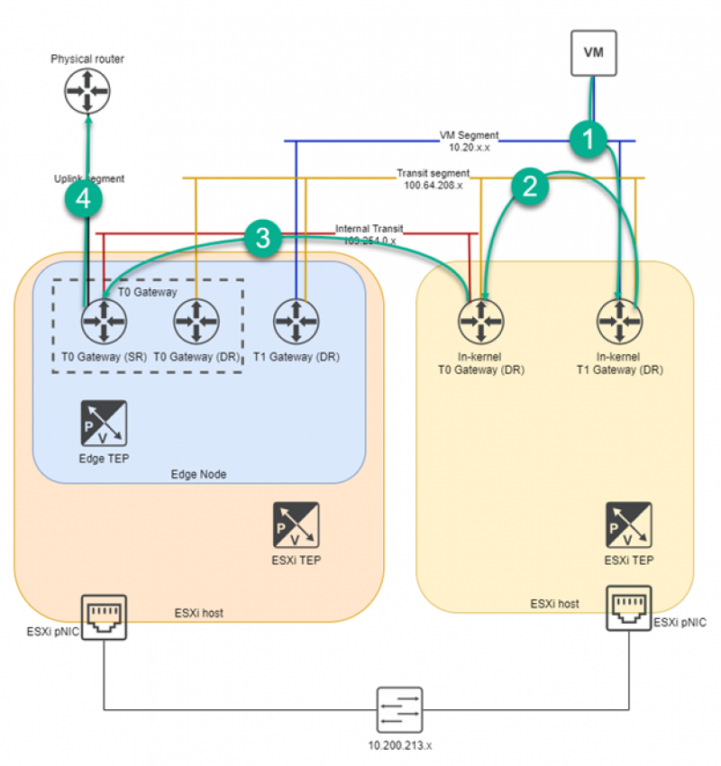
Egress
- VM wants to send a packet to the outside of the environment. It forwards the packet to its default gateway: the T1 gateway Distributed Router (DR) component located on the same ESXi host.
- The T1 router forwards it to its default gateway: the T0 gateway. The T0 gateway also has a DR component on the ESXi host. It uses the T0-T1 transit segment but does not enter the physical network.
- The T0 gateway forwards the packet through its internal T0 network to the Service Router (SR) component located on a different host. This traverses the physical network, see below.
- The T0 SR gateway forwards the packet to the physical environment via VLAN.
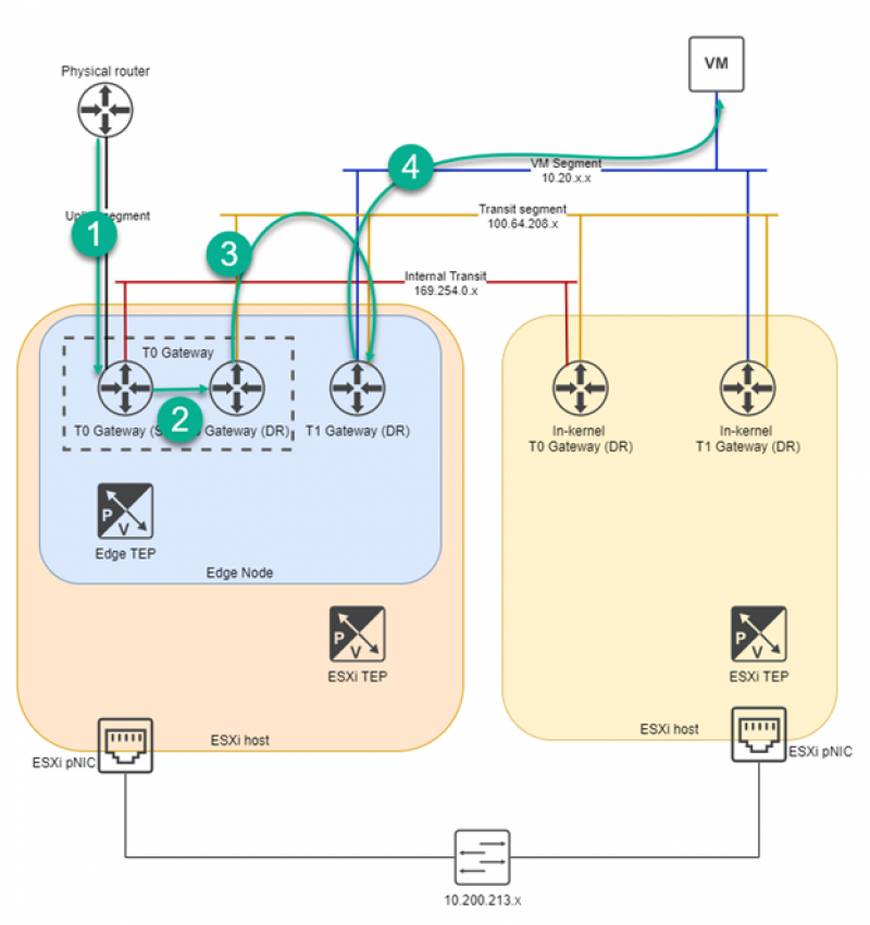
Ingress
- When the packet comes back destined for the VM the physical router forwards it to the T0 gateway SR.
- The T0 SR and DR share a routing table within the Edge Node. It is internally shared to the T0 DR component.
- The T0 DR forwards the traffic to the T1 DR located on the same ESXi host via the Transit segment. It does not traverse the physical network.
- The T1 DR forwards the packet to the VM. This traverses the physical network much like before: the Edge TEP encapsulates the packet, forwards it through the physical network to the ESXi TEP on the ESXi host where the VM resides, where it is decapsulated and forwarded to the VM.
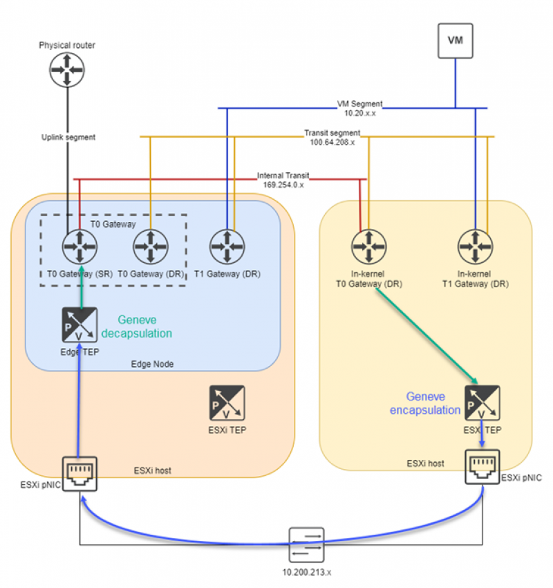
Physical
When a packet has to enter the physical network from one NSX component to another it is encapsulated in a GENEVE packet. This GENEVE packet has an outside layer of source and destination IP of the source TEP and destination TEP. This way the physical underlay only has to look at the TEP to TEP traffic, not the overlay traffic that is encapsulated within.
In order for a packet to move from one ESXi host to another it has to traverse the physical network. This is where GENEVE comes into play.
Each ESXi host and each Edge Node has a Tunnel End Point (TEP).
The Edge Node has its own TEP. When traffic goes to and from the edge node it uses this TEP, not the ESXi TEP. This is why the Edge Node has an N-VDS configured: to house the TEP. Read more about the N-VDS (and other switches) here!
 LinkedIn
 Twitter
Questions, Remarks & Comments
If you have any questions and need more clarification, we are more than happy to dig deeper. Any comments are also appreciated. You can either post it online or send it directly to the author, it’s your choice.